Complete Guide to Manganese Dioxide Catalyst Installation: How to Avoid Clogging and Extend Lifespan?
In industrial waste gas treatment and deep wastewater purification, manganese dioxide catalysts are increasingly favored by enterprises due to their advantages such as high efficiency, low cost, and no secondary pollution. However, many users ask two questions during installation and use: What should be paid attention to when installing manganese dioxide catalysts? Is it prone to clogging? This article will answer these questions in an easy-to-understand way. Improper installation will render even the best catalyst useless. By following these four steps, a solid foundation can be laid for long-term stable operation.
Step 1: "Sieve" Before Installation
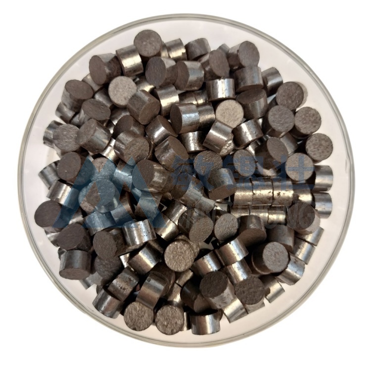
During transportation and loading, manganese dioxide catalysts inevitably produce some fine powder and broken particles. Before installation, it is essential to sieve the catalyst through a 20-100 mesh screen to remove the powder. At the same time, welding slag, rust, and dust inside the reactor must be thoroughly cleaned. This step seems simple, but many malfunctions stem from "laziness"—dust directly enters the bed, clogging the micropores from the outset.
Step Two: Laying the "Base"—The Support Layer A support layer must be laid beneath the manganese dioxide catalyst. This is typically made of inert alumina balls or pebbles, at least 30 cm thick, with larger particles at the bottom and smaller particles on top. The support layer serves three purposes: preventing the catalyst from falling into the inlet and outlet pipes; ensuring more even gas flow distribution; and preventing the catalyst from directly impacting the metal grid and causing wear. One electronics factory, lacking a support layer, experienced significant manganese dioxide particle pulverization after only three months of operation, causing its ozone removal rate to plummet from 99.3% to 81.7%—a very painful lesson.
Step Three: Uniform Filling, Preventing "Groogging" When filling the manganese dioxide catalyst, add it in small amounts multiple times, gently sprinkling it in. Never pour it directly from a height, as this can easily break the particles. After every half meter of filling, gently smooth the surface with a wooden board. The filling thickness should generally be no less than 0.5 meters. Uneven filling will cause the gas to flow along areas of least resistance, creating "grooves"—some catalysts will be overloaded, while others will be idle, significantly reducing overall efficiency.
Step 4: Ensure proper sealing and uniform airflow distribution.
Use ozone-resistant gaskets (EPDM or PTFE) at flange connections, and tighten bolts diagonally. Install airflow distribution plates (30%–50% opening rate) at the reactor inlet and outlet to allow gas to pass evenly through the catalyst layer, as if "queuing up." After installation, test run with low-pressure air to check for consistent pressure drop and ensure there is no air leakage or flow deviation.
II. Is manganese dioxide catalyst prone to clogging? Three types of clogging to distinguish.
Manganese dioxide catalysts are inherently porous and not easily clogged, but clogging can occur under certain operating conditions. There are three common situations:
1. Dust clogging: If the exhaust gas contains a large amount of soot, carbon black, or rust, these solid particles will deposit on the surface and pores of the manganese dioxide, slowly forming a "mud shell," leading to increased resistance and decreased efficiency. Prevention: Install a bag filter or cartridge filter before the catalyst to control the particulate matter concentration below 10 mg/m³.
2. Scale Formation (Limescale)
In wastewater treatment, if the water has high calcium and magnesium ion content (i.e., high hardness), coupled with a local pH increase during the catalytic reaction, calcium carbonate and magnesium hydroxide will form scale on the manganese dioxide surface, firmly covering the active sites. Prevention: Soften the water beforehand, or circulate and clean with a 1%–2% citric acid solution every 3 months to dissolve the scale.
3. Biofilm Formation (Limescale)
When treating wastewater containing organic matter, microorganisms may grow on the surface of manganese dioxide, forming a sticky biofilm. This biofilm not only clogs pores but also consumes oxygen in the water, interfering with the catalytic reaction. Prevention: Maintain residual chlorine in the water at 0.1–0.3 ppm, or periodically flush with a low concentration of sodium hypochlorite.
III. What to Do When Clogged? Backflushing Helps
Once the bed pressure drop exceeds 1.5 times the initial value, or the treatment efficiency significantly decreases, backflushing should be performed immediately—introducing compressed air or clean water from the bottom to flush out accumulated particles and scale. For severe scaling or biofilm formation, a two-step regeneration process of "alkali washing + acid washing" can be used. If the pressure drop remains high after repeated cleaning, it indicates that the manganese dioxide catalyst structure has been damaged and replacement is necessary.
Conclusion: Installing a manganese dioxide catalyst requires four essential steps: screening, support layer, uniform filling, and sealed distribution. For clogging issues, a targeted approach is needed—dust removal through filtration, scaling through softening, and biofilm removal through disinfection. With proper installation and control of operating conditions, stable operation of a manganese dioxide catalyst for over two years is entirely feasible. Hopefully, this article will help you avoid common pitfalls and make your environmental protection equipment more worry-free and cost-effective.
Author: Gloria
Date: 2026-04-21