Language:



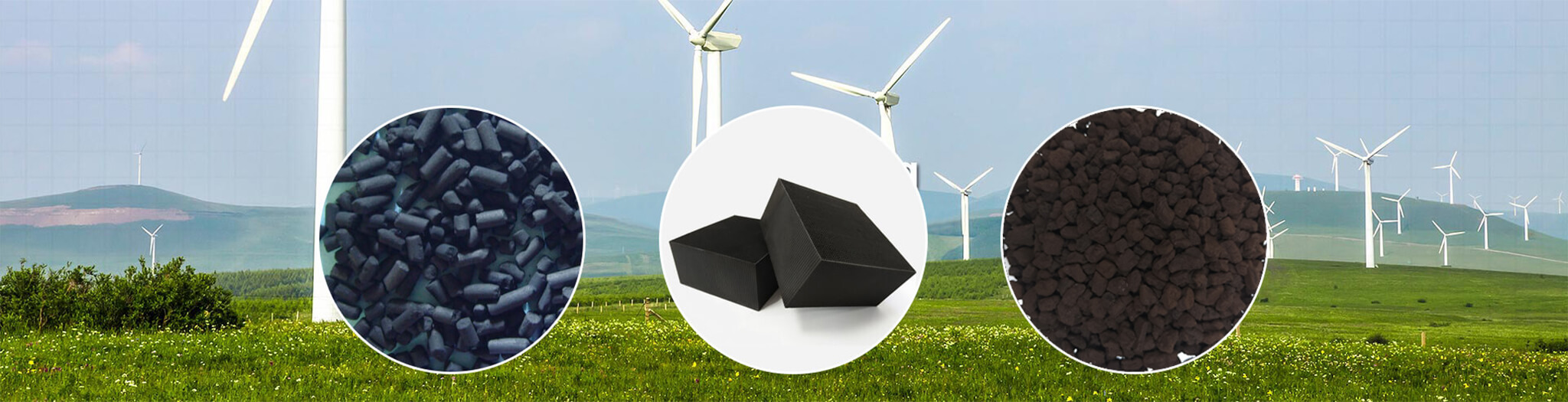
Treatment of carbon monoxide (CO) in cement kiln exhaust is shifting from a process-control byproduct to a rigid environmental compliance requirement. The exhaust gas at the cement kiln preheater outlet typically carries a dust load of 80–100 g/Nm³, with CaO content exceeding 60% in the dust; the flue gas temperature is usually only 120–160°C. Among various end‑of‑pipe technologies—solution absorption, cryogenic separation, adsorption, and catalytic oxidation—catalytic oxidation has become the mainstream route because of its high efficiency, low energy consumption, and lack of secondary pollution. At the heart of catalytic oxidation is the CO catalyst—it must not only answer the technical question of “can CO be oxidized,” but also the engineering question of “can it operate stably” under the harsh conditions of low temperature (120–160°C), high dust loading, and the simultaneous presence of SO₂ and water vapor. Catalyst selection directly determines treatment effectiveness and operating costs.
CO in cement kiln exhaust has two primary sources. The first arises from process control needs—in the calciner and rotary kiln, incomplete combustion under oxygen‑deficient conditions generates CO. Techniques such as low‑NOx burners and staged combustion maintain a reducing atmosphere to reduce nitrogen oxides (NOx), but the resulting CO is not fully combusted and escapes with the flue gas. The second source is the decomposition of organic compounds in raw materials—alternative feeds containing organic carbon (e.g., clay, coal gangue, fly ash, gasification slag) decompose to release CO in the preheater at temperatures between 350 and 600°C.
Emission concentrations vary widely. CO levels in the kiln inlet chamber are typically in the thousands of ppm. The CO volume fraction in cement kiln exhaust is approximately 0.9% on average. When alternative fuels are used, CO in the calciner outlet gas can reach 5000–10000 ppm. Cement kilns co‑processing sludge show higher CO concentrations in their exhaust compared to those without co‑processing.
In terms of emission standards, the China Cement Association approved and implemented the group standard “Ultra‑Low Emission Standard for Air Pollutants in the Cement Industry” in July 2022. In January 2024, the Ministry of Ecology and Environment, together with four other ministries, issued the “Opinions on Promoting Ultra‑Low Emission in the Cement Industry” (Huan Da Qi [2024] No. 5), mandating that, under a reference oxygen content of 10%, the hourly average emission concentrations of particulates, SO₂, and NOx from the cement kiln and waste heat recovery system must not exceed 10 mg/m³, 35 mg/m³, and 50 mg/m³, respectively. The target is to make significant progress by the end of 2025, with 50% of cement clinker capacity in key regions upgraded, and by the end of 2028, 80% of national capacity is expected to complete the upgrade. As the cement industry increasingly adopts alternative fuels and low‑NOx combustion technologies, CO control is gradually being tightened, and CO emission limits are likely to become even more stringent.
Currently, the main end‑of‑pipe CO treatment routes are as follows:
| Technology Route | Principle | Advantages & Disadvantages | Suitability for Cement Flue Gas |
|---|---|---|---|
| Solution Absorption | CO is absorbed by a complexing agent and then desorbed by heating | Recovery can be theoretically high, but the economics are poor | Unsuitable for large‑volume gas streams |
| Cryogenic Separation | Cooling to extremely low temperatures to liquefy and fractionate components | Extremely high capital and operating costs | Difficult to scale in the cement industry |
| Adsorption | Selective adsorption of CO on solid adsorbents | Cannot handle large volumes with complex, multi‑component mixtures | Not applicable |
| Catalytic Oxidation | 2CO + O₂ → 2CO₂, catalyst lowers activation energy | Low light‑off temperature, high efficiency, low energy consumption, no secondary pollution | Optimal choice |
The key advantage of catalytic oxidation is that CO oxidation is strongly exothermic, releasing substantial heat while efficiently removing CO. Given the existing environmental protection infrastructure in cement plants, CO catalysts can be integrated with existing SCR (selective catalytic reduction) deNOx systems, enabling CO oxidation capacity to be added through modest retrofitting. The development of efficient, low‑cost catalysts that are compatible with actual operating conditions is critical for broader industrial deployment.
CO oxidation catalysts can be divided into noble‑metal and non‑noble‑metal types based on the active components.
Noble‑metal catalysts typically contain platinum (Pt), palladium (Pd), or gold (Au). They exhibit high catalytic efficiency, excellent low‑temperature activity, and good resistance to water vapor and sulfur compounds. They can achieve light‑off at relatively low temperatures (e.g., 60°C). However, the scarcity and high cost of noble metals limit their large‑scale application in industrial flue gas treatment.
Non‑noble‑metal catalysts are based on transition metal oxides such as copper (Cu), manganese (Mn), cobalt (Co), and cerium (Ce). They are low‑cost and abundant, and are thus regarded as promising alternatives to noble metals. Copper‑based catalysts, in particular, are among the most effective non‑noble catalysts for CO oxidation, owing to their excellent redox cycling (Cu⁺/Cu²⁺) and strong metal‑support interactions. However, most non‑noble CO catalysts have a light‑off temperature (T10) of 80–120°C, and their complete conversion temperature (T90) typically exceeds 150°C.
For cement kiln exhaust, catalysts must satisfy the following requirements: low‑temperature activity—the flue gas is only 120–160°C, so the catalyst must provide sufficient CO oxidation activity under these conditions; dust resistance—the dust load of 80–100 g/Nm³ with CaO >60% demands high mechanical strength, abrasion resistance, and anti‑blocking properties; sulfur and water resistance—the coexistence of SO₂ and water vapor requires the catalyst to be tolerant to poisoning.
In terms of physical form, honeycomb monolithic structures (e.g., ceramic honeycomb coated with active components) are preferred for high‑volume cement flue gas streams because of their low pressure drop, uniform gas distribution, and large geometric surface area.
The cement kiln exhaust temperature is only 120–160°C. Most non‑noble CO catalysts have light‑off temperatures in the range of 80–120°C, and require temperatures above 150°C for complete conversion. When the gas temperature falls below the catalyst activation temperature, CO conversion drops sharply. For example, a copper‑manganese catalyst achieved 95% CO conversion at 150°C and a space velocity of 10,000 h⁻¹, but the conversion dropped to only 45% when the temperature was reduced to 90°C. In one case, a steel mill’s sintering flue gas de‑CO unit experienced winter gas temperatures of only 70–80°C, and the catalyst averaged less than 40% conversion after just two weeks of operation. Mitigation strategies include using low‑temperature catalysts (e.g., those with trace noble metals that can light off at 60°C), installing flue gas heaters, and optimizing reactor insulation.
The cement kiln exhaust contains a significant amount of water vapor. Water molecules compete with CO for adsorption on active sites and can induce the formation of surface hydroxyl groups that cover active centers. For copper‑manganese non‑noble catalysts, performance degradation becomes particularly pronounced when relative humidity exceeds 60%. In a simulated flue gas containing 12% water vapor at 80°C, an unmodified copper‑manganese catalyst lost activity from 98% CO conversion to 55% within 100 hours. Countermeasures include upstream condensation dehumidification, hydrophobic modification (e.g., Ce or Zr doping, surface silanization), and using monolithic structures to reduce water‑vapor diffusion resistance. A coking plant installed a condensation dewatering device upstream of its de‑CO reactor, reducing inlet water content from 15% to 8% and extending the service life of the same catalyst batch from 6 months to 14 months.
The SO₂ concentration in flue gas is typically 50–500 mg/m³, and can exceed 1000 mg/m³ when burning low‑quality fuels. SO₂ is oxidized to SO₃ on the catalyst surface, which then reacts with active components (CuO, MnO₂, etc.) to form stable sulfates (CuSO₄, MnSO₄), blocking pores and covering active sites. In a flue gas containing 100 ppm SO₂, a copper‑manganese catalyst exhibited a drop in CO conversion from 95% to below 30% after 300 hours of continuous exposure, and the deactivation could not be reversed by thermal regeneration. Cement kiln dust contains large amounts of CaO (>60%) and minor quantities of alkali metals such as K and Na, which can poison catalyst active sites and cause deactivation. Commercial catalysts developed for coal‑fired flue gas often suffer from alkali‑earth metal poisoning in cement kiln applications. Solutions include installing upstream high‑efficiency desulfurization (to reduce SO₂ to below 50 mg/m³), selecting sulfur‑resistant catalysts (e.g., cobalt‑ or ruthenium‑based systems), and using guard beds to adsorb poisons. In a non‑ferrous smelter with flue gas containing approximately 800 mg/m³ SO₂, a conventional copper‑manganese catalyst failed after only 720 hours of operation; after switching to a sulfur‑resistant cobalt‑based catalyst combined with upstream desulfurization, the catalyst life was extended to 6000 hours.
Industrial flue gas treatment often operates at space velocities of 5000–20,000 h⁻¹, corresponding to gas‑catalyst contact times of only 0.18–0.72 seconds. The same copper‑manganese catalyst achieved 92% CO conversion at a space velocity of 5,000 h⁻¹, but conversion dropped to 67% when the space velocity was increased to 15,000 h⁻¹. Strategies to address this include using honeycomb monoliths to reduce pressure drop and increase geometric surface area, optimizing support pore structures by introducing hierarchical macro‑mesopores, and applying thin active‑component coatings to shorten diffusion paths.
The first step in selection is to obtain accurate operating parameters: CO inlet concentration (which can vary from hundreds to thousands of ppm depending on the process), flue gas temperature (120–160°C), gas flow rate and space velocity (5000–20,000 h⁻¹), dust loading (80–100 g/Nm³), and SO₂ and water vapor levels.
Based on these parameters, the following selection guidelines apply:
| Operating Conditions | Recommended Catalyst Type | Rationale |
|---|---|---|
| Temperature <150°C, high conversion required | Low‑temperature catalyst (with trace noble metals) | Light‑off at 60°C, excellent low‑temperature activity, but relatively expensive |
| Temperature >150°C, budget‑constrained | Non‑noble metal (Mn/Cu/Ce‑based) | Low cost, abundant; but complete conversion typically requires temperatures above 150°C |
| High sulfur and high humidity | Sulfur‑ and water‑resistant (cobalt‑based or doped formulations) | Upstream desulfurization to <50 mg/m³ SO₂ significantly extends catalyst life |
| High dust, large gas volume | Honeycomb monolithic, large‑pitch | Low pressure drop, anti‑blocking, large geometric surface area |
Moreover, synergy with existing SCR systems offers a unique advantage for cement plants—CO catalysts can be integrated with existing SCR deNOx infrastructure, allowing CO oxidation capacity to be added through modest modifications. Installing a CO catalytic oxidation stage downstream of the existing SCR reactor minimizes additional capital investment.
The core logic for CO treatment in cement kiln exhaust is that catalytic oxidation is the currently feasible mainstream technology. The catalyst is the heart of catalytic oxidation—its low‑temperature activity, sulfur/water/dust resistance, and durability directly determine treatment performance and operating costs. The low temperature of 120–160°C, high dust load of 80–100 g/Nm³, and the coexistence of SO₂ and water vapor impose far more demanding requirements on catalysts than typical industrial applications. Noble‑metal catalysts offer high activity and excellent low‑temperature performance but are expensive; non‑noble catalysts are cost‑effective but still need improvements in low‑temperature activity and poison resistance. Honeycomb monolithic structures, with their low pressure drop and high geometric surface area, are better suited for the high‑volume cement kiln gas streams. As the cement industry deepens its ultra‑low emission retrofits, CO emission limits are likely to become even tighter. The development of efficient, low‑cost catalysts that are compatible with actual cement kiln conditions will be the key to broader industrial adoption. Catalyst technology is not only a guarantee of compliance but also a critical enabler for the green transformation of the cement industry.
author:Gloria
date:2026-08-11
Contact: Candyly
Phone: 18142685208
Tel: 0731-84115166
Email: minstrong@minstrongchina.com
Add: E2 Building, Kinglory Science And Technology Industrial Park, Wangcheng Area, Changsha, Hunan, China.