Industry new
Selection of Ozone Off-Gas Treatment Technologies and Key Design Considerations for Semiconductor Manufacturing Systems
I. Sources of Ozone-Containing Exhaust in Semiconductor Manufacturing
Semiconductor manufacturing demands highly clean environments and stringent contamination control; ozone is utilized in certain processes as an oxidizing agent or a cleaning medium. Ozone-containing exhaust requiring treatment primarily originates from the following stages:
Ozone-Water Preparation and Wafer Cleaning
Ozone is dissolved in ultrapure water to create "ozone water," which is used to clean wafer surfaces and remove organic contaminants. Typical concentrations range from 2 to 20 ppm, though some processes may reach 50–100 ppm. Ozone can escape during the transport, application, or drainage phases; any undissolved ozone—or ozone released from the water—must be captured and treated, depending on the equipment configuration and exhaust system design. While the flow rate of such exhaust is generally stable, the concentration fluctuates based on the operational status of the process. Therefore, the actual ozone load cannot be estimated solely based on the rated output of the ozone generator.
Ozone-Based Oxidative Exhaust Treatment
In certain nitrogen oxide (NOₓ) abatement processes, ozone is employed as an oxidizing agent to facilitate the conversion of NO into higher-valence NOₓ species. If the ozone dosage exceeds the stoichiometric requirements, or if gas-liquid mass transfer and contact time are insufficient, unreacted ozone may enter the downstream exhaust system. Consequently, both the removal efficiency of the target pollutants and the concentration of residual ozone must be evaluated.
Exhaust from Ozone Generation and Delivery Systems
Ozone-containing exhaust may be generated during equipment purging, maintenance, or operational transitions. The existence and volume of such exhaust should be determined based on the specific equipment design and operational procedures.
Additionally, UV-ozone cleaning systems, corona discharge equipment, and static eliminators used in cleanrooms can generate localized, low-concentration ozone loads. Although the methods for capturing this exhaust may differ from those used for process-related exhaust, these sources must also be included within the scope of ozone control measures.
II. Technical Challenges in Ozone Exhaust Treatment
Fluctuations in Concentration and Flow Rate
The characteristics of exhaust gas from a single piece of equipment can vary significantly across different stages—such as startup, steady-state operation, process switching, and shutdown. Selecting equipment based on a concentration value from a single point in time may fail to account for peak loads. Furthermore, an excessively high flow rate reduces the residence time of the gas within the catalyst bed. Before proceeding with the design, it is essential to determine the ozone concentration and flow rate under normal, peak, and abnormal operating conditions; these data will serve as the basis for establishing design parameters.
Impact of Water Vapor and Liquid Water
Water molecules may compete for adsorption sites on the catalyst surface, thereby interfering with ozone adsorption and surface reactions. The extent of this impact depends on the catalyst material, surface structure, temperature, and humidity levels; it cannot be assumed that an increase in humidity will lead to a proportional decline in catalytic activity. Of greater concern is the condensation of water vapor, which can occur at low temperatures or due to insufficient thermal insulation. If liquid water enters the catalyst bed, it may cause pore wetting, localized blockages, and uneven gas flow distribution, leading to an increased pressure drop and significantly higher risks during long-term operation.
Catalyst Deactivation Due to Coexisting Pollutants
Catalytic performance can be compromised by the deposition of particulate matter, interactions between acidic components and the active phases of the catalyst, or the coverage of active sites by organic compounds and by-products. Since not all semiconductor exhaust streams contain these contaminants, it is necessary to identify the primary interfering species based on the specific process source and actual analytical data, rather than grouping different exhaust systems into a single category.
Requirements for Long-Term System Stability
Beyond ozone decomposition efficiency, factors such as bed pressure drop, equipment sealing, gas flow distribution, temperature fluctuations, and maintenance intervals are critical to ensuring long-term, stable system operation. Issues such as gas flow short-circuiting, excessively high local flow velocities, or uneven catalyst packing can prevent the catalyst material from reaching its full potential activity.
III. Technical Comparison: Thermal Decomposition vs. Catalytic Decomposition
Ozone-containing exhaust gas is typically treated via either thermal decomposition or catalytic decomposition; these methods differ in their underlying reaction principles and operational limits.
Thermal Decomposition
Ozone decomposes into oxygen when heated. Experimental data indicate that at 150 °C, the decomposition rate is only about 28% after 10 seconds, whereas at 250 °C, near-complete decomposition can be achieved within 2 seconds. In industrial applications, the temperature is generally maintained between 250 °C and 350 °C with a residence time of 0.3–0.5 seconds, yielding a decomposition rate of over 95%. For applications requiring higher removal efficiency, temperatures of 400–500 °C and a residence time of approximately 1 second may be employed to achieve near-total removal. Thermal decomposition offers the advantages of a straightforward operating principle and the absence of catalyst consumption. However, it entails high energy consumption due to continuous heating, results in high-temperature exhaust gases, and necessitates considerations for cooling and the safety of high-temperature components. This method is best suited for scenarios characterized by high ozone concentrations, limited airflow, and the availability of waste heat or existing heating infrastructure.
Catalytic Decomposition
Catalytic decomposition facilitates ozone breakdown via active surface sites and can operate at ambient, low, or moderate temperatures. It typically consumes significantly less energy than thermal decomposition and is well-suited for continuous exhaust streams containing low to moderate concentrations of ozone. Nevertheless, actual performance is influenced by factors such as space velocity, humidity, the presence of co-existing pollutants, and bed design; it should not be assumed that all catalysts maintain consistent treatment capacity under ambient temperature and high-humidity conditions.
Selection Criteria
If ozone concentrations are high, airflow is moderate, and a stable heat source or waste heat recovery system is available on-site, thermal decomposition should be considered first. Conversely, if the exhaust stream contains ozone in the ppm to tens-of-ppm range, involves high airflow, is characterized by continuous emissions, and lacks significant interference from co-existing components, catalytic decomposition is generally the more economical choice. In cases involving high humidity or complex pollutant compositions, the final selection—regardless of the chosen method—must be based on empirical data validated under actual operating conditions.
IV. Evaluation and Selection of Ozone Decomposition Catalysts
Catalyst selection should not be based solely on initial decomposition efficiency; rather, it should be evaluated across four dimensions: active components, humidity tolerance, structural configuration, and long-term stability.
Active Components and Reaction Mechanisms
Ozone decomposition catalysts are primarily categorized into manganese-based transition metal oxides and noble metal-supported materials. MnO₂-based materials, which utilize the Mn⁴⁺/Mn³⁺ redox cycle to facilitate electron transfer, are the most widely used in industrial applications due to their relatively low cost. Copper-manganese composite oxides can further enhance electron transfer and surface adsorption capabilities through the synergy of multiple oxidation states. Noble metal-based systems (e.g., Pt, Pd, Ag) often exhibit superior stability under humid conditions, though at a significantly higher cost. Composite systems, such as Ag/MnO₂, retain the cost advantages of manganese-based catalysts while offering improved moisture resistance, making them a viable option for high-humidity operating environments. Selection should be based on empirical data—specifically performance under the target concentration, space velocity, and humidity conditions—rather than relying solely on the material’s name or classification.
Humidity Adaptability
For exhaust streams originating from ozonated water generation or wet cleaning processes, water vapor and mist droplets are critical variables. The following must be verified:
Decomposition efficiency across the actual humidity range;
The impact of humidity fluctuations on catalytic activity and pressure drop;
Performance recovery capability following prolonged exposure to humidity;
The necessity of pre-treatment steps, such as mist elimination or gas-liquid separation.
In operating conditions where condensation is a risk, the system design should prioritize preventing liquid water from entering the catalyst bed, rather than attempting to resolve the issue by replacing the catalyst.
Structural Configuration and Space Velocity Matching
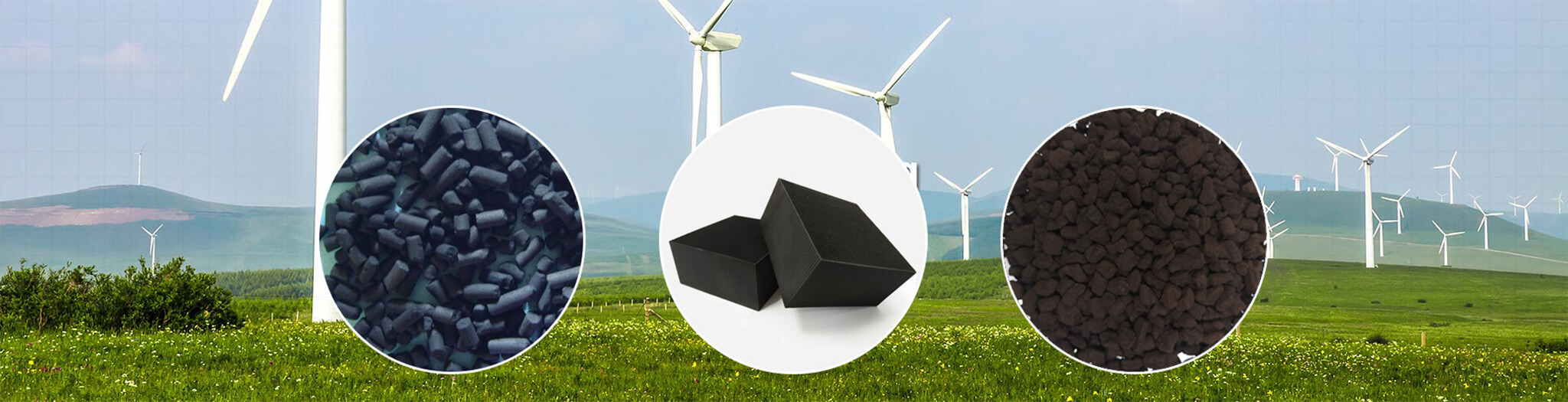
Granular catalysts offer flexible loading options, though high airflow rates necessitate careful consideration of bed pressure drop and gas flow distribution. Honeycomb-structured catalysts feature uniform channels; with proper design, they can balance throughput and contact efficiency, though performance remains dependent on channel dimensions, the distribution of active components on the channel walls, and gas velocity. For semiconductor cleanroom applications, the design space velocity typically ranges from 10,000 to 50,000 h⁻¹, while for industrial ozone exhaust systems, the common range is 5,000 to 50,000 h⁻¹. The upper limit of space velocity is constrained by the required contact time, while the lower limit is dictated by engineering feasibility regarding equipment volume and pressure drop. Catalyst loading quantities should be determined based on empirical test data and the target outlet concentration.
Mechanical Strength and Long-term Stability
During continuous operation, catalysts are subjected to gas-stream erosion, mechanical pressure from the bed load, and fluctuations in temperature and humidity. Insufficient mechanical strength can lead to fragmentation, pulverization, and the loss of catalyst particles, which in turn adversely affects pressure drop and gas flow distribution. For honeycomb catalysts, particular attention should be paid to structural integrity, coating adhesion, and stability under thermal and humidity cycling.
V. Engineering Design Considerations for Catalytic Decomposition Systems
The catalyst is merely one component of the overall system; effective and stable treatment also depends on gas collection, pre-treatment, bed design, and monitoring infrastructure.
Exhaust Collection Efficiency
If ozone-containing gas is not collected effectively, the overall control objective cannot be achieved, regardless of how efficient the downstream treatment equipment may be. The collection system should be designed based on the configuration of exhaust ports, process chambers, and ductwork. It is essential to evaluate variations in exhaust flow rates under different operating conditions to prevent fugitive emissions caused by insufficient collection capacity.
Determination of Catalyst Loading and Space Velocity
Space velocity is calculated by dividing the volumetric gas flow rate by the catalyst volume; both values must be based on consistent reference conditions. While initial estimates for space velocity can be derived from empirical data for similar operating conditions, the final catalyst loading should be determined by considering the catalyst’s measured performance—under the target concentration, temperature, humidity, and space velocity—along with the required outlet concentration. Relying solely on the space velocity formula is insufficient to account for fluctuations in concentration and flow rate during actual operation.
Space Velocity (GHSV) = Volumetric Gas Flow Rate ÷ Catalyst Volume
Gas Distribution and Bed Structure
If gas is concentrated in a specific area, it can lead to high local flow velocities and "short-circuiting," resulting in the underutilization of a portion of the catalyst. Design considerations should focus on uniform gas inlet distribution, the cross-sectional area of the catalyst bed, the uniformity of catalyst loading, and the integrity of the support structure. For systems with high airflow rates, structural design measures should be implemented to minimize variations in local flow velocity. Furthermore, the pressure drop across the catalyst bed must be factored into fan selection and the assessment of energy consumption over the system's entire lifecycle.
Humidity Pretreatment
For exhaust streams containing mist droplets or posing a risk of condensation, components such as demisters, gas-liquid separators, or thermal insulation and heat tracing may be required, depending on the dew point, duct temperature, and the catalyst's moisture tolerance. It should be noted that dehumidification is not a mandatory step for catalytic treatment systems; its necessity depends on specific operating conditions. Excessive dehumidification can lead to unnecessary energy consumption and increased equipment complexity.
VI. Safety, Compliance, and Operational Boundaries
Ozone treatment systems involve considerations regarding occupational health, emission compliance, and equipment safety; therefore, operational boundaries must be clearly defined during the design phase.
Occupational Exposure and Emission Control
According to the Chinese standard GBZ 2.1—2019, the maximum allowable concentration of ozone in the workplace atmosphere is 0.3 mg/m³. OSHA sets an 8-hour time-weighted average (TWA) limit of 0.1 ppm (approximately 0.2 mg/m³), while NIOSH recommends an upper limit of 0.1 ppm. In the semiconductor industry, a concentration below 0.1 ppm is typically used as a safety benchmark. Regarding emissions, some regions have established local pollutant discharge standards for the semiconductor industry (e.g., Shanghai’s DB31/374—2024). Before connecting to a facility-wide exhaust (fab-wide) system, it is essential to verify whether that system is equipped to handle ozone and to confirm compliance with applicable local discharge requirements. The mere fact that exhaust gas is routed into a facility’s exhaust piping does not imply that it can be discharged directly into the environment.
Material Compatibility and Corrosion Protection
Due to its high oxidation potential, ozone accelerates the aging or corrosion of stainless steel, aluminum alloys, rubber seals, and polymer piping. Components that come into contact with ozone—such as pipes, valves, seals, and instrument connections—must be made of compatible materials. Furthermore, the replacement cycle for these components under long-term exposure should be evaluated during the design phase.
Safety Interlocks and Monitoring
Thermal decomposition systems must be equipped with temperature monitoring, over-temperature alarms, and heater interlocks. For catalytic systems, particular attention should be paid to abnormal catalyst bed temperatures, sudden spikes in ozone inlet load, and potential leaks through bypasses. Ozone detection instruments should be installed at exhaust collection points, at the inlets and outlets of treatment equipment, and in areas where personnel might be exposed; these should be integrated with ventilation controls or system shutdown logic.
Environmental and Safety Considerations for Catalyst Replacement
Spent (deactivated) catalysts may have adsorbed acidic components or organic substances. During replacement, risks such as dust exposure must be assessed, and the waste must be characterized and disposed of in accordance with relevant regulations—it should not be treated as ordinary solid waste.
VII. System Performance Verification and Catalyst Status Assessment
Following installation, the system’s treatment capacity must be verified through actual operational testing; compliance cannot be determined solely based on design specifications or the initial performance of the catalyst.
Inlet/Outlet Concentration Testing and Efficiency Calculation
Sampling points should be established both upstream and downstream of the catalyst bed to measure ozone concentrations under identical or comparable conditions. The ozone removal efficiency is calculated as follows:
Removal Efficiency (%) = [(Inlet Concentration – Outlet Concentration) / Inlet Concentration] × 100%
If there is a significant difference in gas flow rates between the inlet and outlet, the actual mass flow rate should be calculated to evaluate the total amount of ozone removed, rather than relying solely on concentration changes to assess overall performance.
Coverage of Representative Operating Conditions
Testing must encompass a range of scenarios, including normal and high ozone concentrations, varying airflow rates, and actual humidity levels. Additionally, system performance during process transitions and load fluctuations should be carefully monitored. Data obtained solely under conditions of low concentration, low flow rate, or dryness are insufficient to reflect the treatment capacity under actual production conditions.
Determining the Need for Catalyst Replacement
Ozone decomposition catalysts do not simply "wear out" after a fixed period; with proper design and routine maintenance, MnO₂-based catalysts typically have a service life of 3–5 years. The decision to replace a catalyst should be based on a comprehensive assessment of the following indicators, ensuring that any observed issues are not actually caused by external system factors:
A sustained increase in outlet ozone concentration, despite constant inlet load and airflow. While this is the most direct indicator, one must first rule out system-related causes, such as an increase in ozone generation, bypass leakage, or a decline in fan performance.
A significant increase in the pressure drop across the catalyst bed. This may be caused by the accumulation of particulate matter, oil mist coverage, the ingress of condensate, or catalyst pulverization leading to blockages; an increased pressure drop also results in higher energy consumption for the fan.
Physical degradation—such as fragmentation, pulverization, clumping, or abnormal coloration—observed during a shutdown inspection. The risk of clumping is higher under conditions of high humidity or condensation. For honeycomb-structured catalysts, the structural integrity and the adhesion of the active coating should also be examined.
Approaching the design service life. Even if the outlet concentration currently meets standards, it is advisable to perform a performance evaluation (via sampling) after long-term operation. If the compressive strength has decreased by more than 30%, or if the proportion of particles meeting size specifications has fallen below 80%, the catalyst is likely nearing the end of its service life.
When an increase in outlet concentration or an abnormal pressure drop occurs, first investigate the inlet load, airflow distribution, humidity, pre-treatment facilities, and ductwork sealing. Only after ruling out these system-level issues should one conclude whether the catalyst requires regeneration or replacement.
VIII. Conclusion
The core challenge in treating ozone-containing exhaust gas—such as that found in semiconductor manufacturing—lies not in selecting a single "most efficient" technology, but in aligning the chosen technical approach with specific parameters: concentration, flow rate, temperature, humidity, co-existing components, and the required continuity of operation. Thermal decomposition is suitable for scenarios where heating is feasible and ozone concentrations are high, whereas catalytic decomposition—provided it is properly designed and validated—is better suited for continuous exhaust streams with low to medium ozone concentrations. Regardless of the path chosen, any treatment solution must be grounded in empirical operating data. By matching catalyst materials and structures, controlling space velocity, optimizing gas flow distribution, and defining clear safety and compliance boundaries—while continuously monitoring outlet concentrations and catalyst bed pressure drop—it is possible to translate "catalyst activity" into a practical, long-term, and sustainable treatment capacity.
Author: Gloria
Date: 2026/11/19